 |
 |
|
Meade field tripod mod's |
Go back to HOMEPAGE
|
|
|
|
Meade field tripod mod's |
Go back to HOMEPAGE
|
September 10, 2009 Yeah, my telescope has made it here from Colorado. I've set it up in my office to have a look, and my initial impression is that it is very sturdy and well built. I can't wait to get it outside! |
| September 18, 2009 I was able to set up the telescope tonight and have a look at Jupiter with it...so cool. The tripod was relatively easy to setup, but perhaps a little shaky. |
| November 6, 2009
Well, I've had a month and a bit to assess the tripod, and I have come to the following conclusions:
I consider these issues to be relatively minor to the usage of the telescope itself, but since they are relatively simple to fix, I plan to do so. Stay tuned! |
| November 27, 2009
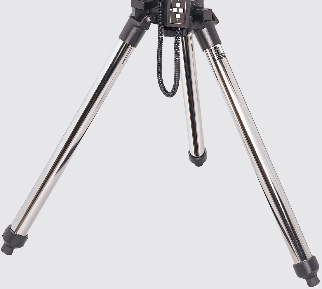
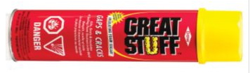
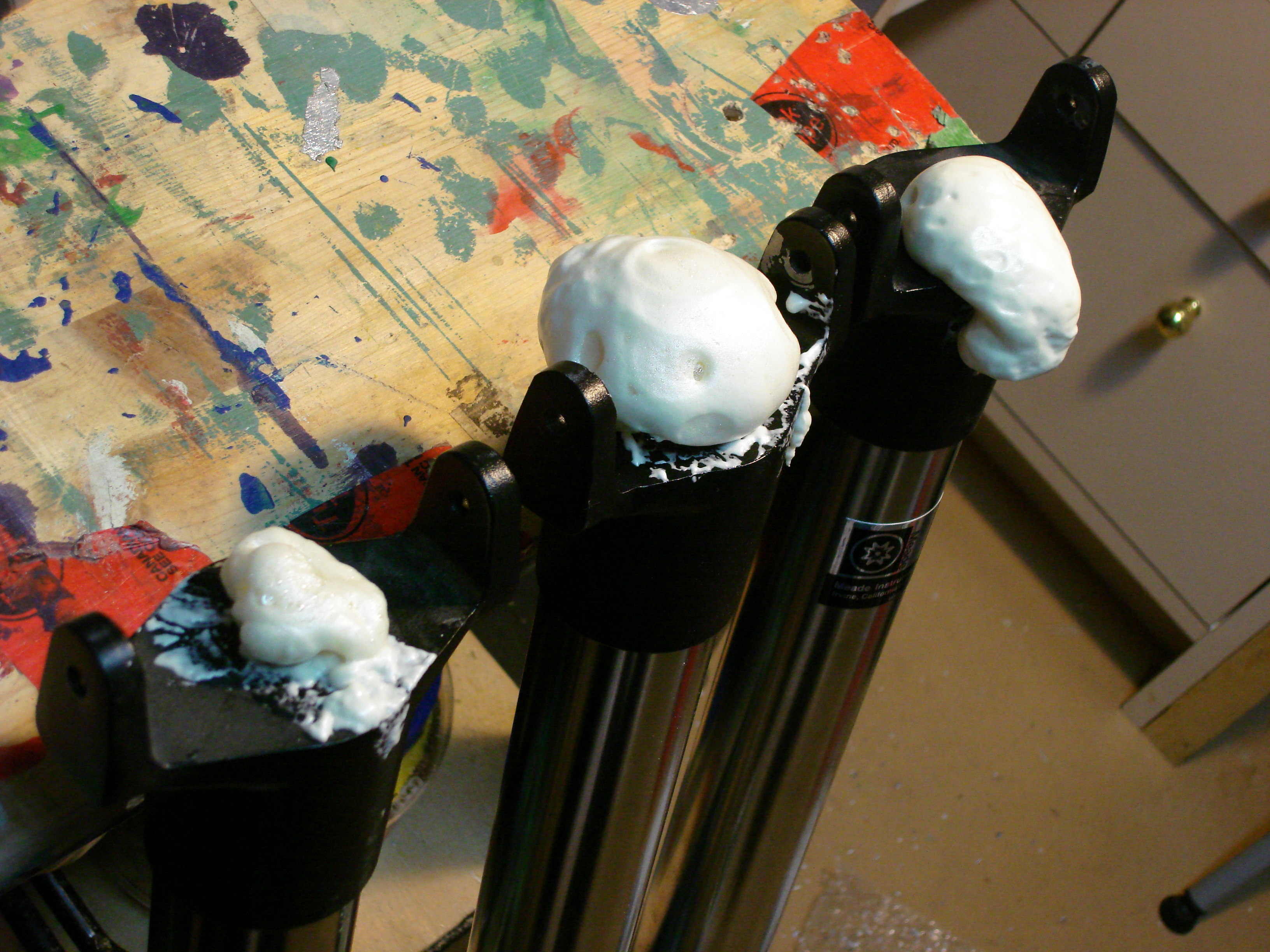
#3 Stiffen Legs So, how to stiffen the legs without adding a lot of weight, hmmm. Perhaps filling the empty cavity of the metal tubing with something lightweight but rigid would do the trick. My mind immediately went to that amazing polyurethane expanding foam that you can buy for plugging gaps around window and door installations. It is light weight, expands to fill the volume, cures rigid, and is cheap at $5 a can.
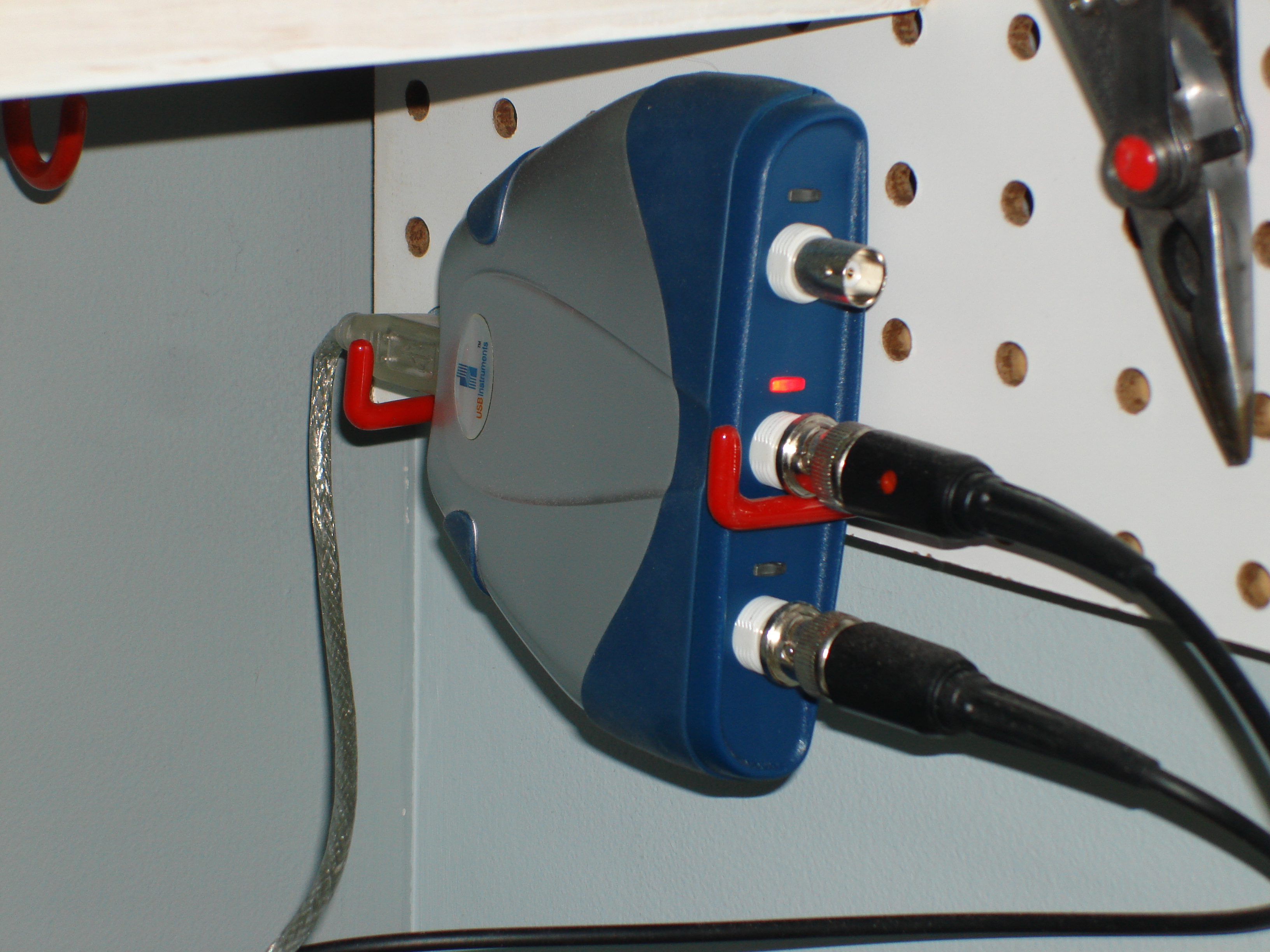
Before I went ahead and recommended this fix to anybody else, I wanted to be sure that it was in fact improving matters. To do this I employed some of my engineering knowledge and performed a "rap" test. Essentially I attached an instrument that responds to vibration onto one of the legs, banged the leg with a hammer before and after I put the foam inside, and then compared the results. I didn't really feel like setting up proper accelerometers and the whole data acquisition system from work, so I put together a make-shift system that gave me what I needed. I crazy glued an old piezo-electric buzzer I had to the middle of the leg, and attached the leads to my USB oscilloscope (yes, I am a nerd). The buzzer and a proper accelerometer are essentially the same thing, a piece of quartz crystal between to electrodes. To my pleasant surprise the response from the buzzer was great! My peak voltage from a hammer hit was around 10V and the background noise level was only around 30 mV, an SNR of 333...sweet!
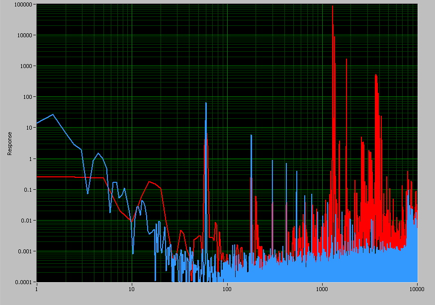
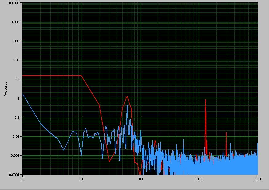
Before doing the rap test I did a quick hand calculation to figure out what the 1st harmonic for the leg should be. Assuming a simple hollow tube made of carbon steel and pinned at each end, I got 1234Hz. The rap test data from before the foam was added was amazingly exactly what I was expecting! The image below is the power spectral density (PSD) plot generated from the measured data. The blue curve is the response of the buzzer when it is still (ie. back ground system noise). Note the very clear spikes in the blue curve at 60, 180, etc that are due to electrical noise. The red curve shows the response from the leg during the rap. The 1st mode is clearly visible at ~1250Hz as well as its harmonics at 2500 and 3750. Another major response also shows up at around 1800Hz along with a number of lesser harmonics. The data also suggests that there is maybe some kind of low frequency mode at ~17Hz, but is is very poorly defined on the red curve due to the short sample length (~1.5 sec), and may not actually be a real response from the leg but a response from me moving (one end of the leg was in my hand during the rap).
After the empty rap was completed, I drilled a whole in either end of the leg into which I could spray the foam. I drilled 9/32" holes since I intend to tap the one in the bottom to add an adjustable foot. In hindsight however I should have drilled a larger hole in the top of the leg as the 9/32" was too small to let the air rush out of the leg around the applicator straw as the foam went in. The back-up of air resulted in it "farting" wet foam everywhere when I took the applicator straw out of the hole...a sticky sticky mess. Did I mention it was sticky? Oh, and by the way, the foam doesn't wash off either.
The rap test of the foam filled leg did not yield as good PSD data because the sample time was extremely short, about 0.2 seconds. Considering the fact that my objective was to have the leg vibrations dampen themselves out more quickly, the short sample length was in-of-itself a sign that my experiment had been successful. The PSD plot that I was able to get from the test data showed that the main high frequency tones are still present, but greatly attenuated. The sample was far too short to get any meaningful resolution around the lower frequency responses, but I don't think anything is happening there anyway.
The more telling proof that my diabolical plan was successful is the plot comparing the time history of the vibration data, with and without the foam. It is very clear that the addition of the foam reduces the time it takes for the oscillations in the leg to dampen out. Based on my data, vibrations in the legs die out approximately 16x faster with the foam in. The cost in weight for this great improvement is minimal. I measured the density of the foam to be about 0.0375 g/cm^3, which results in there being about 60g of foam per leg...peanuts! I used about 2/3 of one can of the foam.
|
| November 30, 2009 Well the foam thing has ended up being a bit of a pain. Apparently the single part foam that I used needs moisture in the air to cure properly. I found this out after finding that a couple days later the legs seemed to respond like they were hollow again. When I drilled through the end of the cured foam, I found that the cured part was only an inch or so deep, and that all the foam on the inside had turned back into a liquid. Doh! After several experiments with partial filling, and continuously poking a hole in the ends to let air in, the method that seemed to work was putting a little bit of water into the leg first. After spraying the foam in behind the water, I kept rolling and shaking the legs to make sure the foam was getting exposed to the water. The idea worried me as water staying in the leg meant the possibility of corrosion. In the end, the foam expanded and pushed pretty much all the water out. A wet mess, but it did seem to result in all the foam curing properly. If you intend to try this mod, I highly recommend getting the other version of this foam that is 2-part. This type cures by chemical reaction, not reaction with water in the air, and is perfectly suited for this application...I know this now after having wrestled with the 1-part stuff! It is supposed to be available from contractor supply stores as it is used commonly in the commercial construction business. |
| December 18, 2009 I was kind-off proud of my little leg foam experiment, so I wrote a letter summarising my work and sent a copy blindly to Meade and Celestron. I addressed the letters to their main headquarters in California, attn: Engineering Department. Surprisingly I actually got a very nice response from Meade via email. I heard nothing from Celestron. My letter to Meade, and their response can be found in PDF format below. |
|
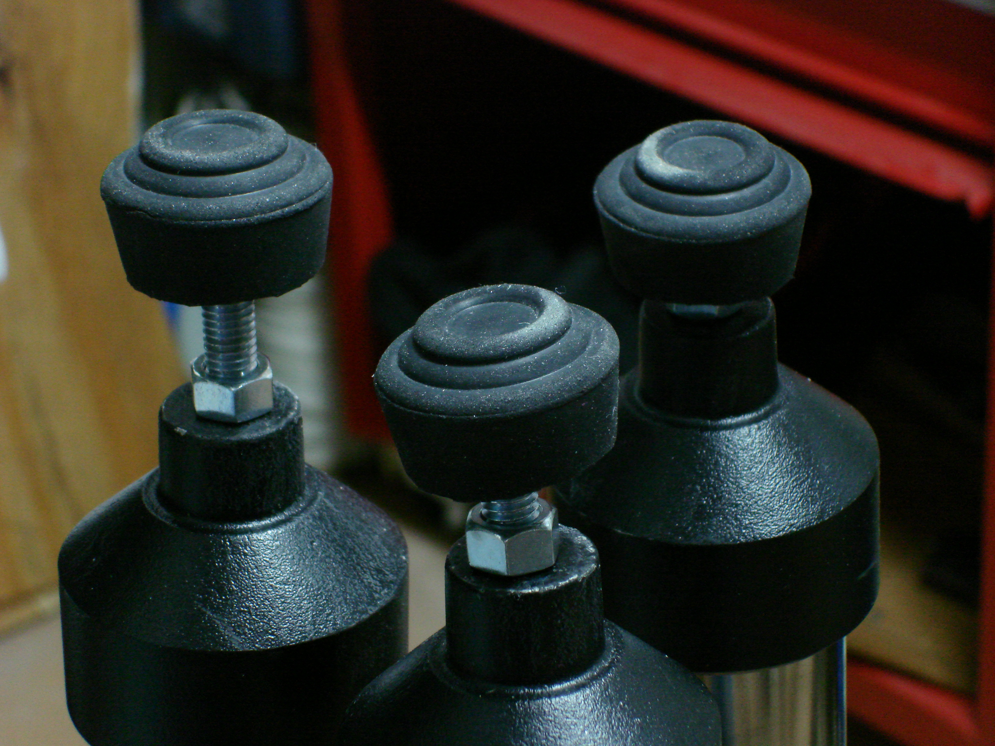
February 20, 2010 #1 Adjustable Feet With the legs filled with foam long ago, it was now time to get off my butt and do the other upgrades I have on my list, starting with finishing the adjustable feet. I tapped the holes I had drilled in the bottom of each leg with a 3/8-16 UNC tap (pic 1a). I then epoxied big rubber feet onto the 3/8 x 3” carriage bolts that I had selected to use (1b). When the epoxy was dry I added a 3/8 jam-nut for locking, and then screwed them into the legs (pic 1c). Easy.
1a. |
|
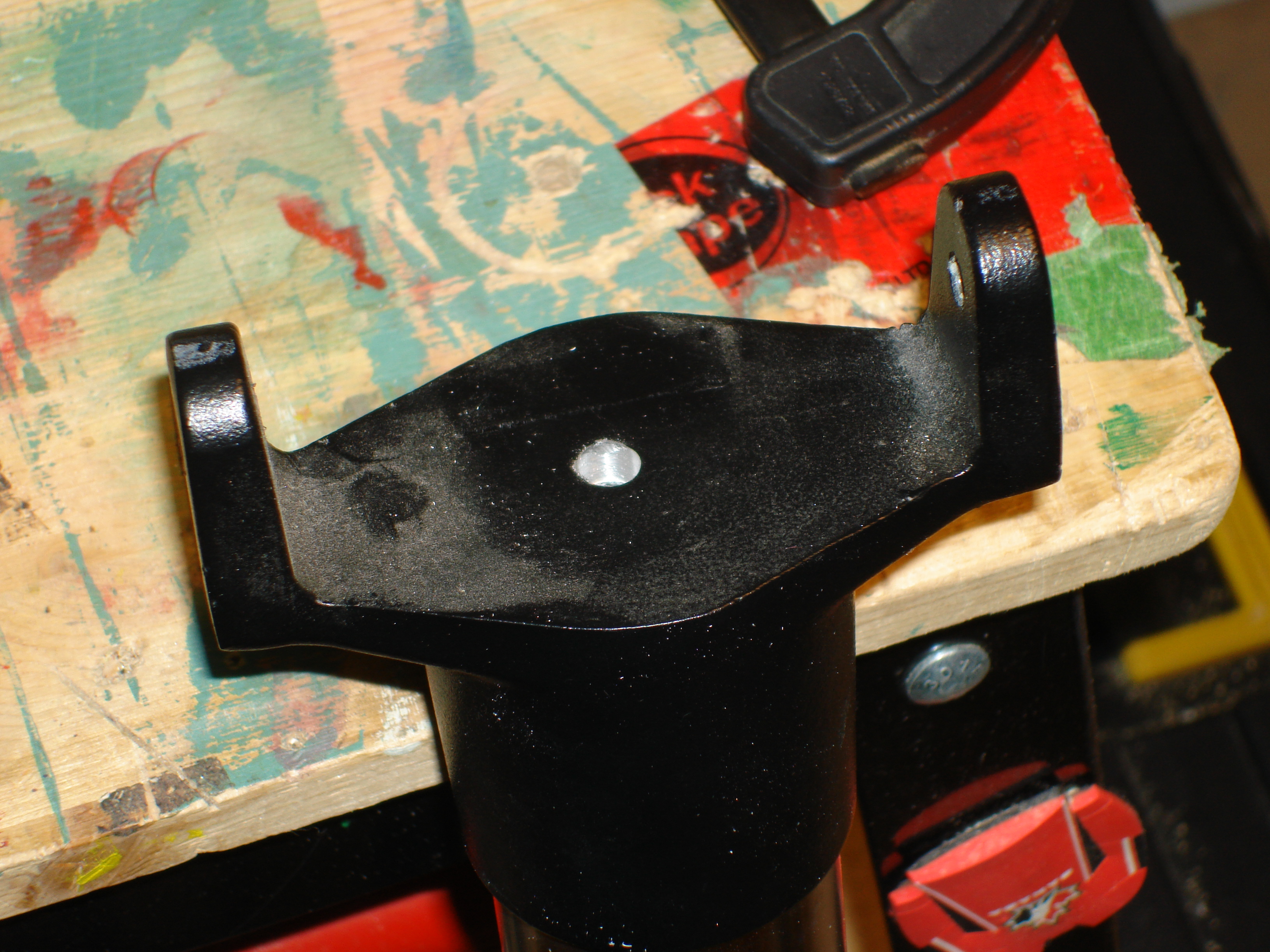
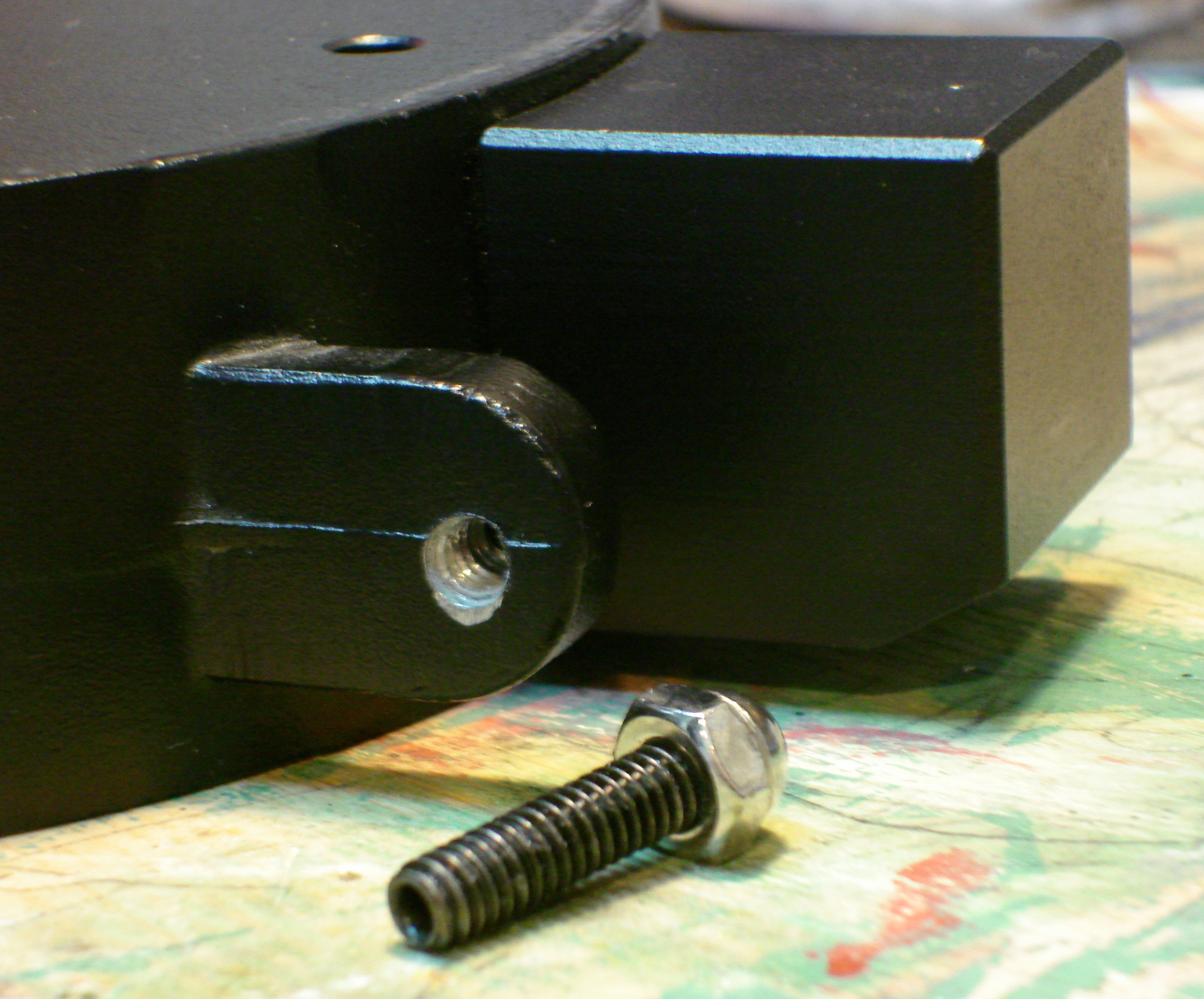
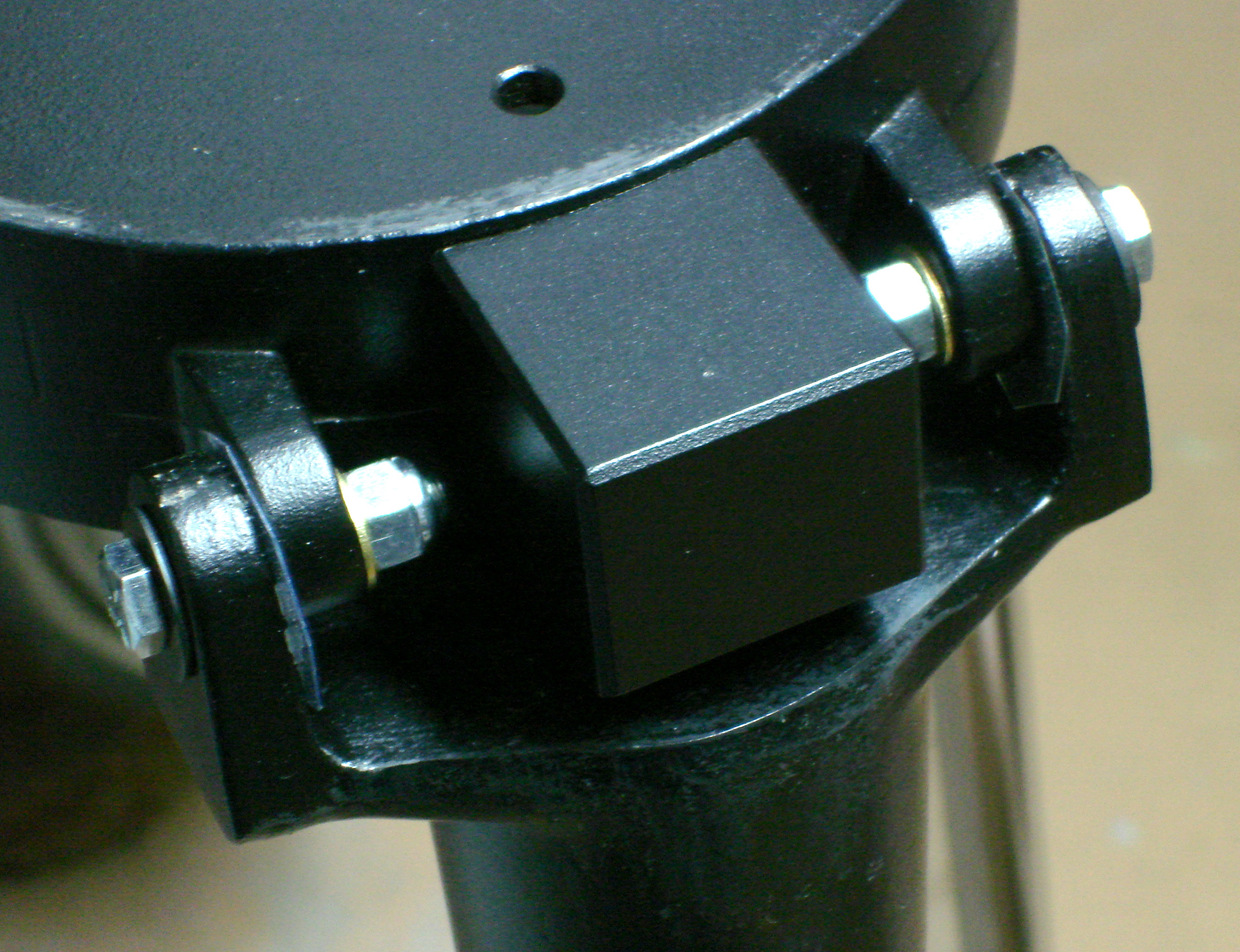
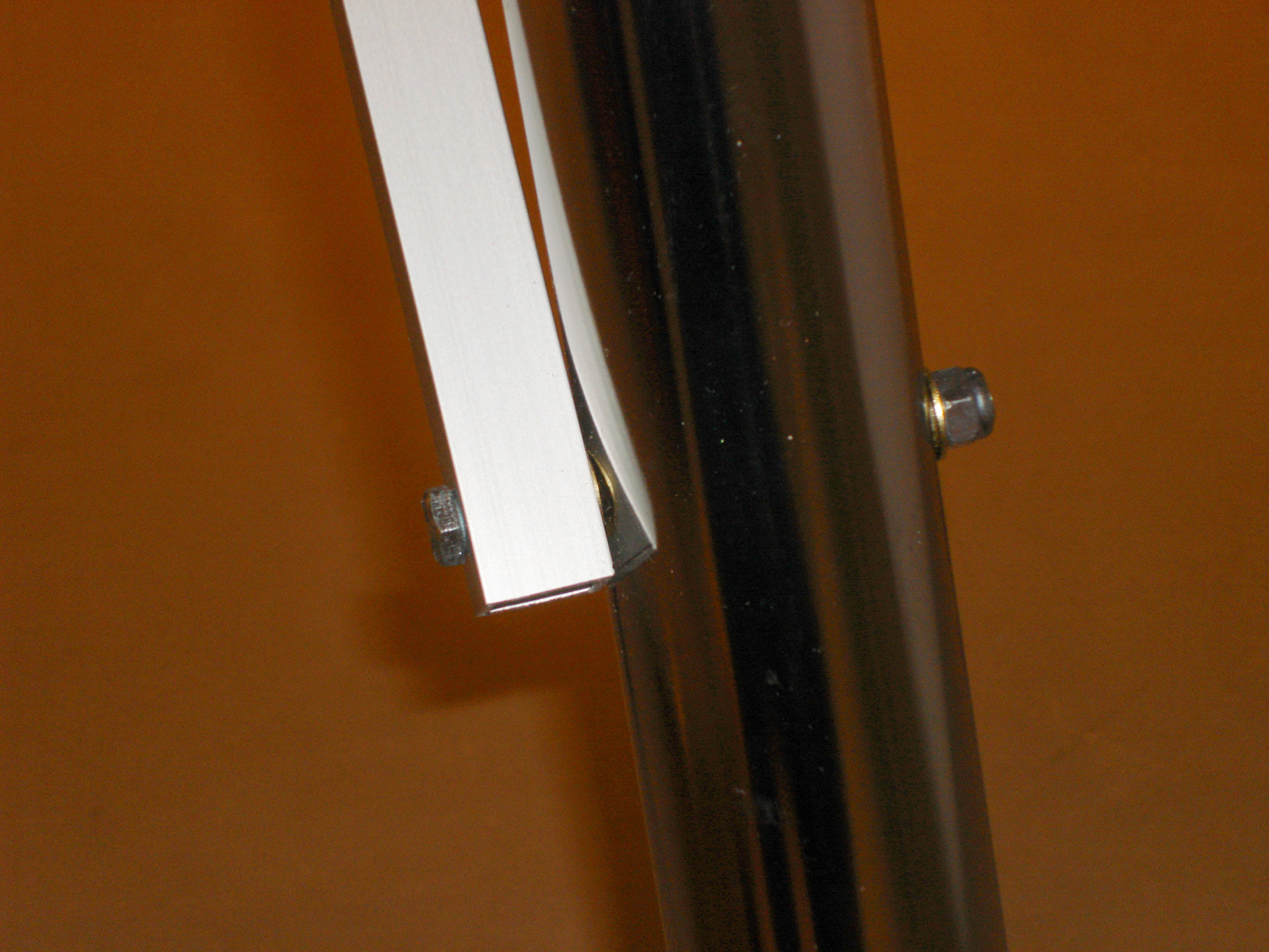
February 27, 2010 #4 Leg-to-Base Connection As mentioned earlier in this blog, the way in which the legs attach to the tripod base is not great (pic 4a). Tightening the funky bolts puts stress on the aluminum casting that can result in the threads stripping or worse, the casting cracking. Since having nice snug legs is important to the tripod’s stability, it was important to me to come up with a better attachment method. I decided to through bolt the legs, using plastic washers to make up the small gap between the leg and base tabs. I started by drilling out the ¼-20 threads in the tripod base with a ¼” drill (pic 4b). I then re-assembled the legs with ¼” hex-head bolts and nylock nuts. I did this step with the stop blocks not in place so that I had lots of room to work. The end result is I can tweak the tension on the leg bolts to get them nice and stiff, without worrying about stressing the aluminum castings (pic 4c).
4a. |
|
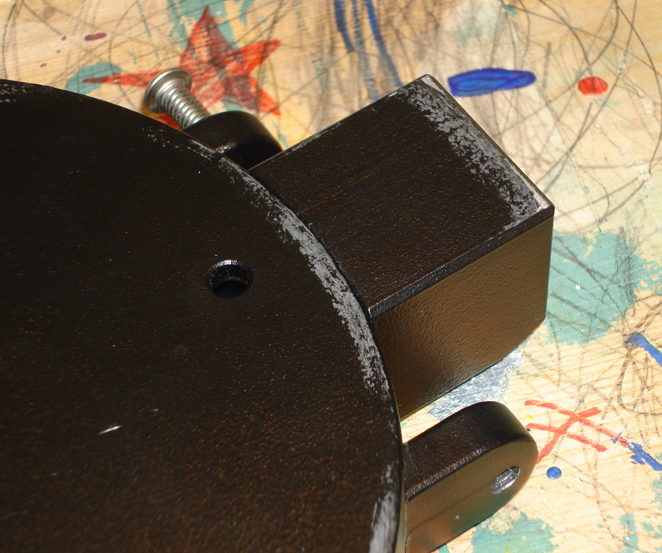
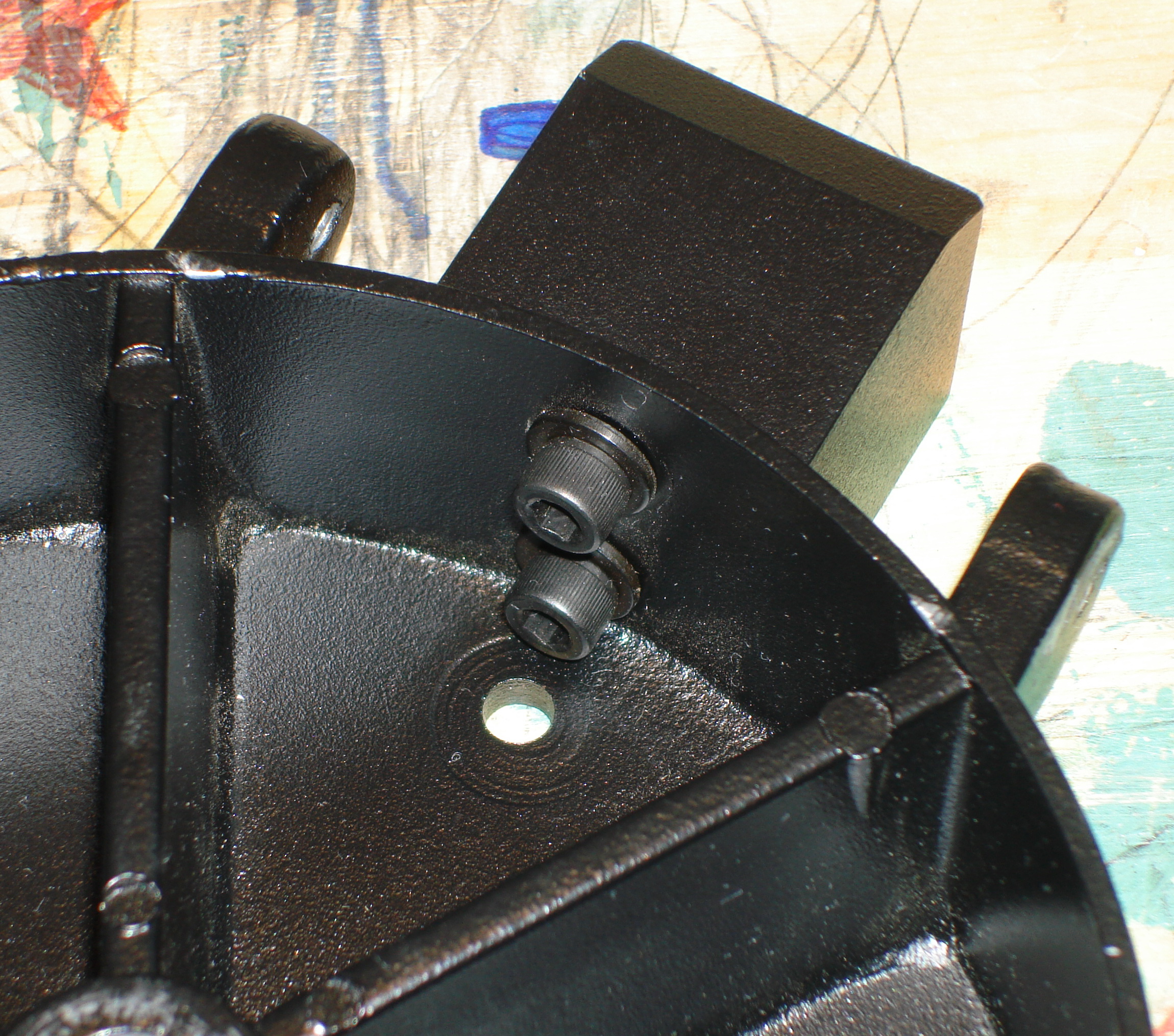
February 28, 2010 #2 Crooked Stop Blocks After some closer examination, and disassembly, it became evident that the reason the one stop block was sitting high and rubbing on the wedge (pic 2a) was that the holes in the tripod base through which the block is bolted are way oversized for the machine screws being used (pic 2b). This allows the block to move back-and-forth or up-and-down by 1/8” or so. Only the friction of the block against the base keeps it from moving. I re-assembled the blocks to the base with them sitting as low as the holes would allow. I put thread lock on the block mating surface as well as the threads of the machine screws. Hopefully nothing will move now, and the blocks will remain well out of the way of the wedge.
2a. |
| March 14, 2010
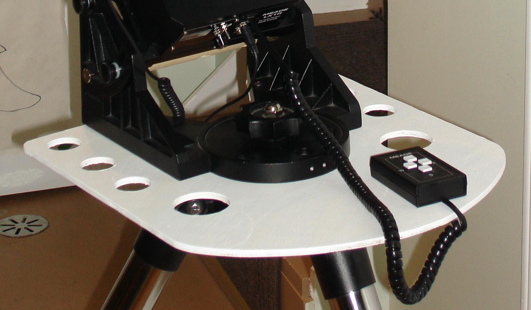
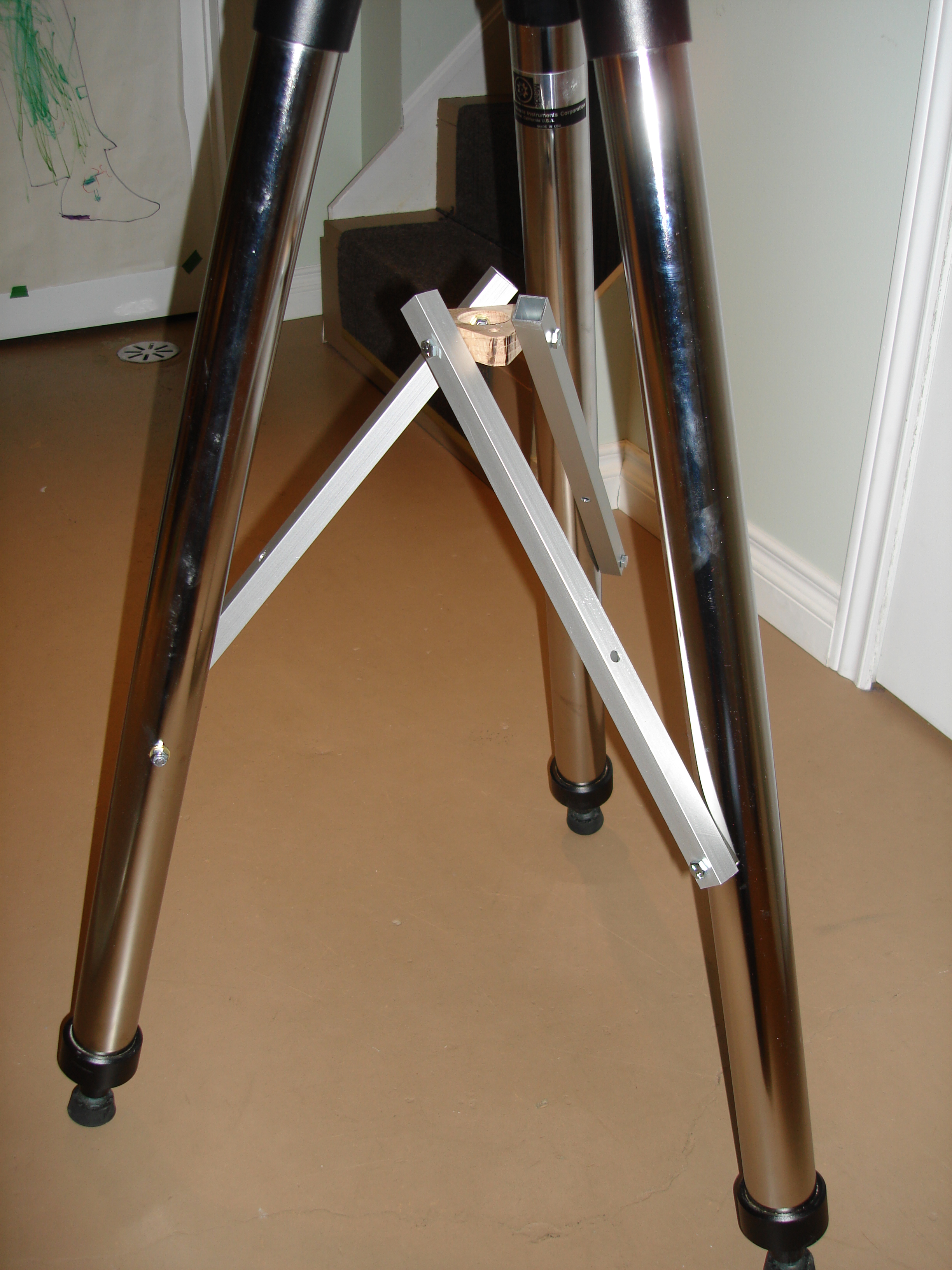
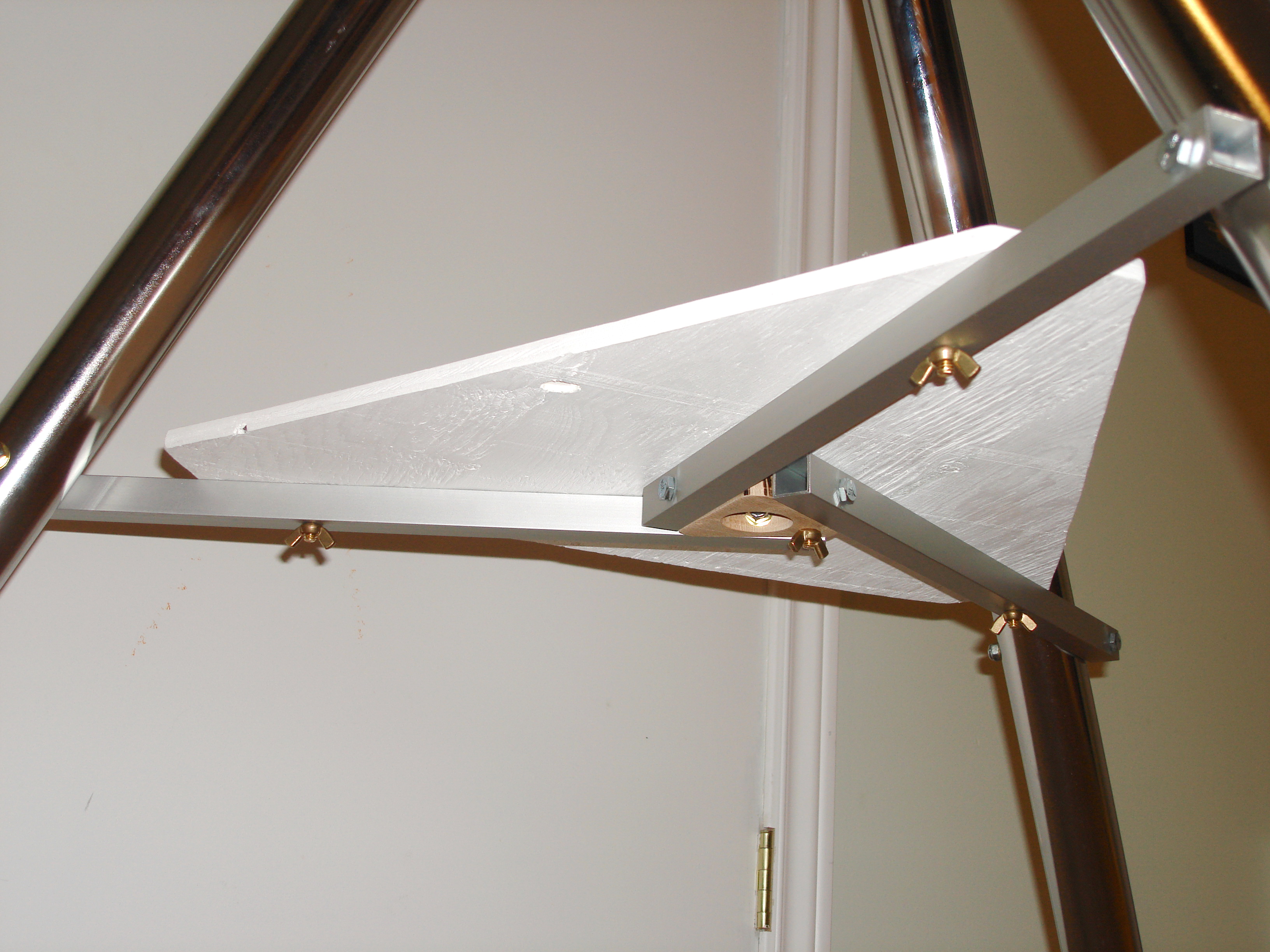
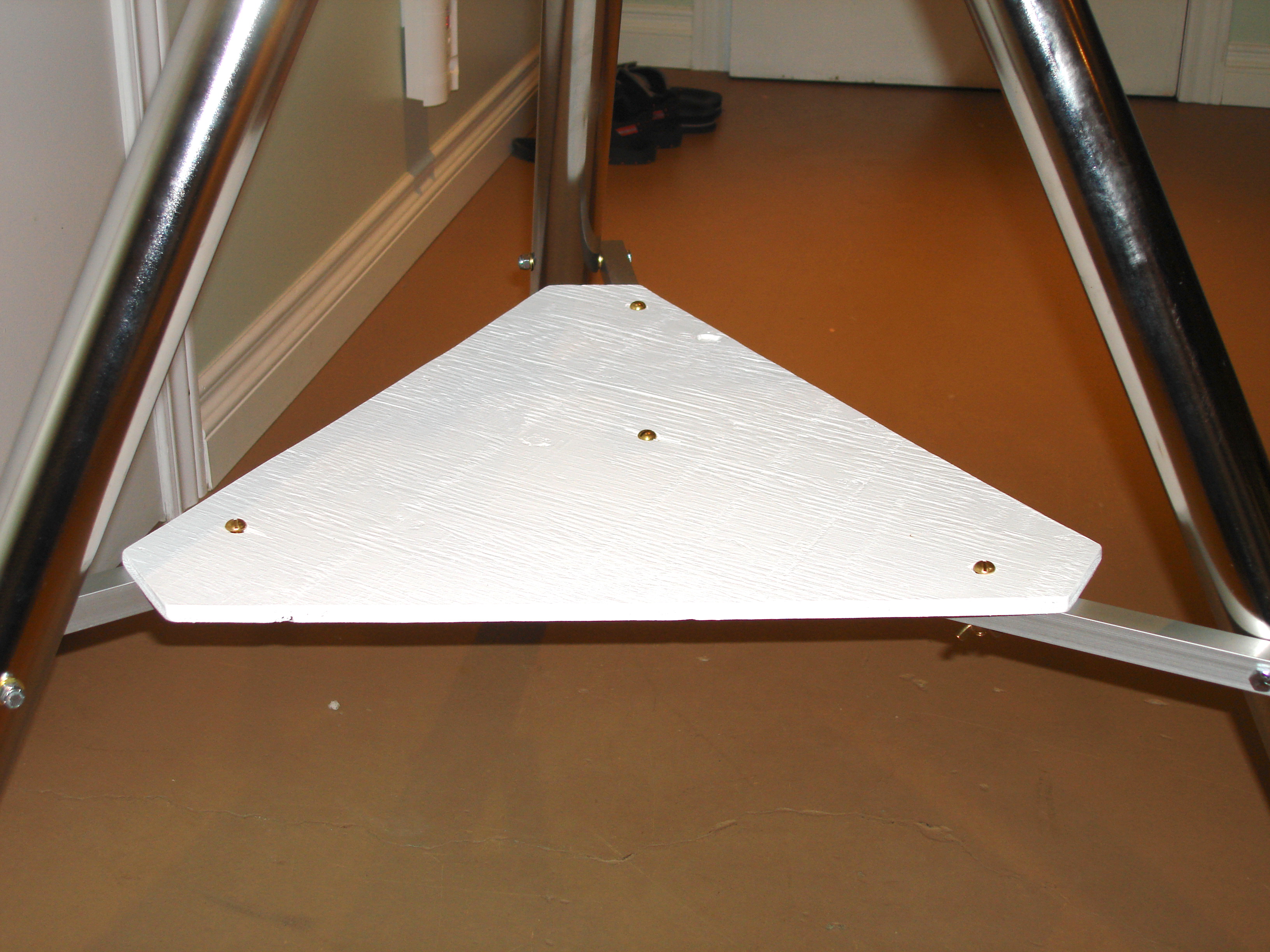
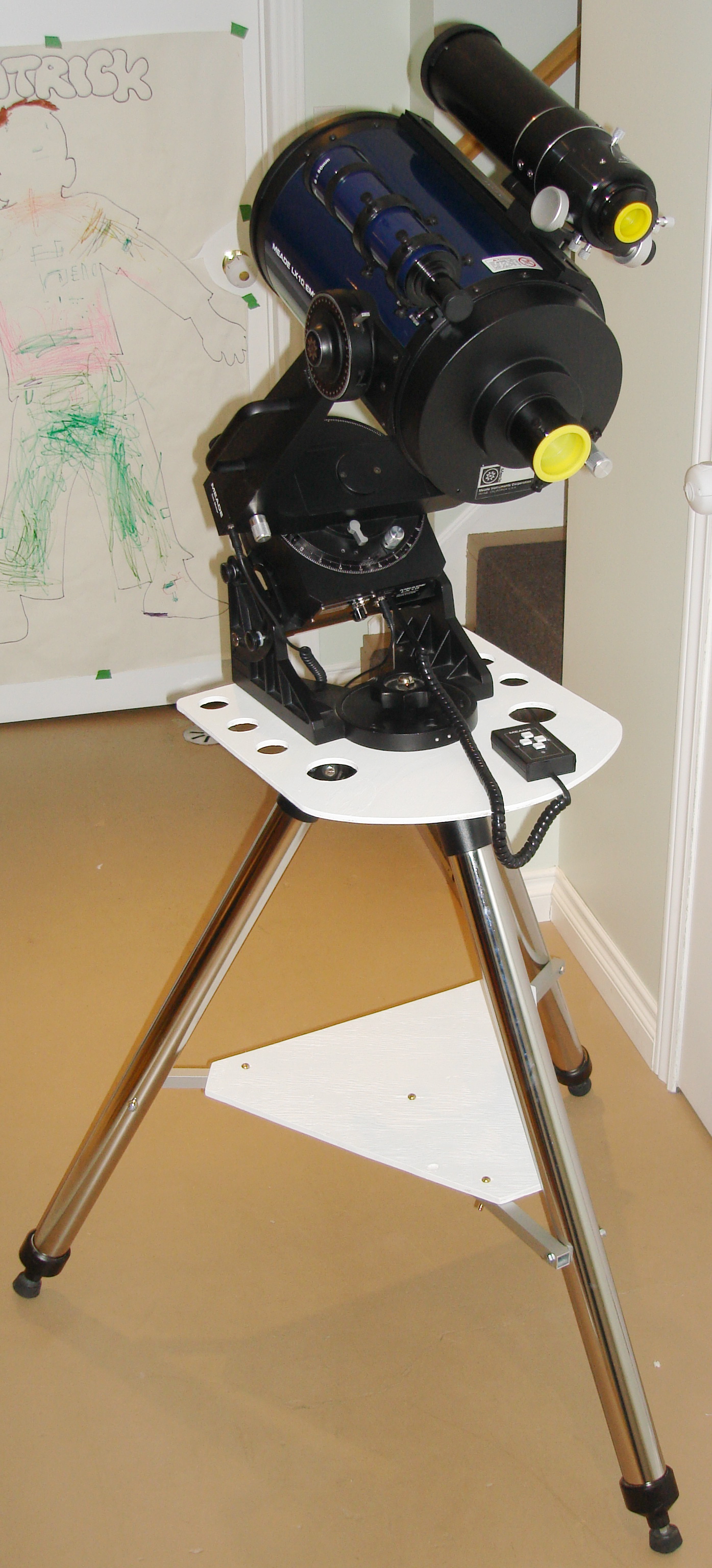
#5 Shelves The basic LX-10 field tripod does not come with an eypiece tray like a lot of other tripods, so for sure I wanted to add some place for eyepieces. This was a pretty easy modification to make. I just used some scrap 3/8" plywood I had laying around, and sketched up a shape for the shelf that fit will with the wedge, and that did not stick out too much and interfere with viewing through the telescope. I added some holes for eyepieces, and then gave it a coat of white paint. Voila, done (5a). The eyepiece shelf is held on the tripod simply by sandwiching it between the tripod base and wedge. I also thought it would be handy to have a shelf lower down that I could put my maps or laptop on. This was a little trickier since I wanted to come up with a slick way of attaching the shelf to the tripod legs that wasn't too much of a pain to take on and off when the tripod was folded up for storage. I toyed with with a number of ideas, but finally ended up on a folding idea. Attached approximately half way down each tripod leg there is a 3/4" square aluminum tube (pic 5b). The tube is bolted through the leg, and is free to swing up and down. The three aluminum tubes then join in the middle at a triagular shaped plate (pic 5c) made out of 3/4" red oak (just what I had laying around). The tubes are bolted and free to swing at the centre plate as well. When all bolted together, the centre plate moves up and down as the legs are closed and opened (pic 5d), the aluminum tubes and centre plate all being in a common plane when the tripod legs are fully opened. I then through drilled each aluminum tube and the centre plate so that I could bolt a triangular shaped 3/8" plywood shelf to the them when in the fully open position (pic 5e & 5f). When all bolted together the tripod is impressively solid, sweet! (pic 5g) 5a. 5g.
|
Go back to HOMEPAGE
Last updated: 30-May-10
|
Copyrights to all content from the webpages hosted here belongs to Jim Thompson. Nov. 2009. |